![<?echo $_SERVER['SERVER_NAME'];?>](/template/twentyseventeen/skin/images/header.jpg)
1. No-flow signal output check and take measures
1.1 Causes of Failure
1) Power failure.
2) Connection cable (excitation circuit, signal loop) failure.
3) Failure of liquid flow conditions.
4) Damage to sensor components.
5) Failure of converter components.
1.2 Troubleshooting and Taking Measures
1) Check power failure.
First check the main power supply and the magnetizing current fuse. If the new fuse is connected to the specified current value and then re-energized and then blown, the fault must be found. Check whether the output voltage of the power circuit board is normal, or replace the entire power circuit board.
2) Check the connection cable system failure.
Check whether the cables connecting the excitation system and the signal system are respectively connected and whether the connection is correct.
3) Check the liquid flow direction and the liquid filling in the tube.
The direction of liquid flow must match the direction of the arrow on the sensor housing. For the positive and negative measurement of sewage flowmeter, if the direction is not consistent, it can still be measured, but the set display flow forward and backward direction does not match, must be corrected. If the pipe is not full of liquid, it is mainly the pipe network engineering design or sensor installation position. If the sensor is installed in the a, e position and the dotted line discharge b position, it should be converted to c, d position, see figure. 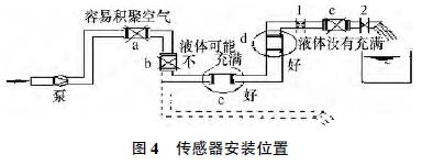
4) Check sensor integrity.
Mainly check the integrity of each terminal and excitation coil. Exciting coil and its system faults often occur: a) the coil is disconnected; b) the insulation of the coil or its terminals drops. The frequency of occurrence of insulation drop in the second type of fault is relatively high. Coil disconnection and insulation drop can be easily checked using a multimeter and a megohmmeter.
5) Check converter failure.
Sewage flowmeter converter check method is often used to replace the circuit board spare parts test troubleshooting.
2. Output shaking causes, check and take measures
2.1 Causes of Failure
1) The flow itself fluctuates or fluctuates. It is not a malfunction of the sewage flow meter. It only reflects the flow condition truthfully.
2) The pipe is not full of liquid or contains air bubbles.
3) External stray currents such as electrical and magnetic interference.
4. 2. 2 troubleshooting and taking measures
1) The fluctuation of the flow itself.
If the flow itself fluctuates, the output shake of the instrument is a true reflection of the fluctuation. The inspection method can be used to inquire the operators and process technicians on the site of use or inspect whether there is any source of fluctuation. Whether there is a vortex in the upstream flow pipe of the sewage flowmeter. On pipelines with pulsating flow sources, the effect of measuring the flow meter is slowed down, usually by taking the flow sensor away from the pulsating source, using pipe flow resistance to dampen the pulsation, or by installing a chamber called a passive filter in the appropriate place in the pipeline. Shock absorber absorbs pulsation.
2) The pipe is not full of liquid or contains bubbles in the liquid. This type of fault is mainly due to bad pipe network engineering design. The sensor's measuring pipe is not filled with liquid or the sensor is not properly installed. There is no back pressure or back pressure in the downstream of the sensor. If it is installed in position e, the flow of liquid through the downstream section is a short section of the atmosphere, if the valve 2 is fully open, the sensor measurement tube may not be full of liquid. Sometimes the flow rate of the fluid is high enough to fill the instrument and the instrument is running normally. If the flow rate decreases, there is a possibility that the liquid will not be fully charged and the instrument will be abnormal. The liquid contains gas and the output signal shakes more. The liquid contains tiny bubbles that gradually accumulate at high or dead spots during the flow, covering the electrodes and causing output sloshing.
3) External electromagnetic interference.
Sewage flowmeters are vulnerable to external interference due to small flow signals. The main sources of interference are stray currents, static electricity, electromagnetic waves, and magnetic fields. The stray current of the pipeline mainly depends on the good grounding protection of the sewage flowmeter. Usually, the grounding resistance should be less than 10 Ω. Do not share the grounding with other motors and appliances.
3. Zero instability check and take measures
3.1 Causes of Failure
1) The pipe is not full of liquid or contains air bubbles.
2) Subjectively, there is no flow in the pipe system but there is actually a tiny flow; in fact, it is not a failure of the sewage flow meter but a true reflection of the misunderstanding of the flow conditions.
3) The sensor is not perfect ground due to stray currents and other external interference.
4) Causes of liquids (such as liquid conductivity uniformity, electrode contamination, etc.).
5) The signal circuit insulation drops.
4. 3. 2 troubleshooting and taking measures
1) The pipe is not full of liquid or contains air bubbles.
See also Pipe is not filled with liquid or liquid with bubbles.
2) Micropipeline flow.
This type of fault is mainly caused by poor sealing of the pipeline's shut-off valve, slight leakage detected by the sewage flow meter, misunderstanding of zero-point change or zero-point instability.
3) Improper grounding is influenced by external interference and changes in ground potential.
External disturbance effects such as stray currents in the pipeline are mainly due to the good grounding protection of the sewage flowmeter. Usually, the grounding resistance is less than 10 Ω. Do not share the grounding resistance with other electrical appliances.
4) Check the liquid properties.
The liquid conductivity changes or is non-uniform, which causes the zero point to change when it is at rest and causes the output to oscillate when flowing.
If the liquid contains impurities, or impurities are deposited on the inner wall of the measuring tube, or the inner wall of the measuring tube is fouled, or the electrode is contaminated with grease, etc., zero point change may occur. The measure is to remove the dirt and sediment layer; if the zero change is large, try to re-zero.
5) Check signal line insulation.
The signal circuit insulation decline will form zero instability. The main reason for the decrease of the insulation of the signal circuit is caused by the decrease of the insulation of the electrode part, but it cannot be ruled out that the insulation of the signal cable and its connection terminals is lowered or destroyed. Because sometimes the on-site environment is very harsh, and the instrument cover, wire connections are inadvertently sealed, filled with moisture acid mist or dust particles intruded into the instrument terminal box or cable protection layer, so that the insulation down. The insulation resistance of the signal loop is checked in two parts, the cable side and the flow sensor side, and tested with a megohmmeter. Divided into two.
a) Fill the liquid measuring electrode surface with the liquid contact resistance flow sensor signal line. Use a multimeter to measure the resistance between each electrode and the grounding point. The resistance between the two electrodes to the ground should be between 10 ~20!
b) Empty tube measuring electrode Insulating and venting the measuring tube, with a dry cloth on the inner surface, until completely dry, measure the resistance between the electrode and the ground with a H500 VDC megohmmeter. The resistance must be above 100M Ω.
4. Check and take measures for inconsistency between flow measurement value and actual value
4.1 Cause of the fault
1) The converter settings are incorrect.
2) The sensor is not installed properly. It is not full or the liquid contains air bubbles.
3) Untreated signal cable or cable insulation degradation during use.
4) The sensor upstream flow conditions do not meet the requirements.
5) Change in sensor inter-electrode resistance or electrode insulation drop.
4.2 Troubleshooting and Taking Measures
1) Review the converter settings and check the zero and span values. First check the number of matching sensors and converters. Most modern sewage flow meters in the manufacturer's real-flow calibration are marked with the sensor's brand name (or attached with the "operating instructions") to indicate the calibration meter constants, and set in the matching converter. Therefore, before the new instrument is commissioned, it is necessary to first check the instrument constants and whether the sensor number and the converter number are matched. Because such mismatch events happen from time to time, it is necessary to review the settings such as caliber, range and unit of measure.
2) Check the fluid condition and whether it contains air bubbles.
This type of failure is mainly caused by poor design of the pipe network engineering or related equipment is imperfect, can refer to the pipeline is not full of liquid or liquid content containing a little air bubbles.
3) Check the signal cable system;
Check whether the connection cable is properly connected? Is the connection correct? Is the insulation lowered?
Usually people check the cause of the failure of the flow meter to measure the flow rate, and often neglect to connect the cable system between the sensor and the converter, often encounter the following examples:
a) Cut off the attached whole cable and reconnect it. After one stage of connection, inhale moisture and reduce the insulation.
b) The end of the signal line is not handled well, and the inner shield, outer shield and signal core are shorted to each other or short-circuited to the housing;
c) No specification (or accompanying) cable;
d) The cable length exceeds the upper limit of the length constrained by the conductivity of the liquid;
e) The conductivity of the liquid is low and the sensor and converter are far apart.
4) Investigate sensor upstream flow conditions.
The flow status upstream of the sensor is often limited by the installation space and deviates from the specified requirements. For example, if the flow path is close to the spoiler and there is not enough straight pipe length, these factors will affect the measurement accuracy. In particular, if the proximity sensor is equipped with a regulating valve or a fully open gate valve, the only solution that can be satisfactorily resolved is to change the installation position of the sensor. In the case of an insufficient length of the upstream straight pipe section, adjust the installation position.
5) Detect contact resistance and electrode insulation between electrode and liquid;
The contact resistance between the electrode and the liquid mainly depends on the contact area and the liquid conductivity.
When filled with domestic and industrial water with a conductivity of 150 × 10 -6 s/cm, the electrode-liquid contact resistance is approximately 15 kΩ. The electrode insulation resistance should be greater than 100 MΩ.
Light Tower is normally used for night lighting in municipal,highway bridges,ports,mines,construction sector construction and other fields, and also suitbable for night repair and disaster scene.

FURD trailer mounted light tower:
- Metal halide lamp and LED lamp optional
- 6 meter or 9 meter safe and quick mast;
- China diesel generator or Honda gasoline generator, high performance;
- Large service dimension for easy maintenance;
- Easy to move with trailer types.
FURD walk behind light tower and Balloon Light Tower:
- Famous motor and generator, excellent performance, start easily;
- Metal halide lamp has long service life;
- Anti-fall, safe and solid;
- Hand-operated winch, lockable at any moment;
- Elevating frame is made of Stsainless steel square pipe;
- Elevating frame can rotate, east for light waving, overturn to intake,transport and store;
- Plastic treated, anti-rust, anti-corrosion and beautiful.
FURD factory also produce the below machines:
Vibratory Road Roller Laser Screed , Power Trowel , Road Repair Machine, Road Marking Machine.
For more information of our products, please feel free contact with us, we are at your service for 24 hours.
Light Tower
Light Tower,Led Light Tower,Outdoor Light Tower,Industrial Light Tower,Emergency Light Tower
Jining Furuide Machinery Manufacturing Co., Ltd. , https://www.vibratoryroller.nl