![<?echo $_SERVER['SERVER_NAME'];?>](/template/twentyseventeen/skin/images/header.jpg)
Summary:This article is for the reasons such as TA model and variable ratio selection, secondary wiring, whether the secondary load can meet the TA10% error curve, a commutation and secondary current circuit grounding methods, which may cause misoperation of the differential protection. Conduct analysis to take measures against actual situations to prevent such accidents.
I. INTRODUCTION Differential protection is the main protection method of the transformer. The principle is to reflect the difference between the inflow and outflow currents at each end of the protected transformer. In the protection zone, the current in the differential circuit is greater than the setting value, and the differential protection instantaneous Actions, and outside the protected area, transformer differential protection should not act. Transformer excitation current, wiring, TA (current transformer;) error and other factors, so that the differential circuit produces unbalanced current, unbalanced current excitation current in the presence of, often can lead to transformer differential protection misoperation It is difficult to realize transformer differential protection. Therefore, the analysis of the causes of common misoperations of transformers, so that the adoption of measures to reduce the occurrence of misoperation of transformers is the main contradiction that needs to be resolved to achieve differential protection of transformers.
Second, the common cause of misbehavior 1. TA model and the choice of transformation error Transformer differential protection should be selected with an air gap of the D-class core TA, because of differential protection on each side of the TA, the voltage level, transformation ratio Both the capacity and the magnetic saturation are inconsistent, and there is always an unbalanced current flowing in the differential circuit. The degree of core saturation directly affects the size of the unbalanced current, and it increases significantly with the increase of the primary current, and the short-circuit current is very large. In order to reduce the unbalanced current, it is necessary to take measures in the TA structure, core material, etc., so that the primary side is not easily saturated with large short-circuit currents. The D-class core TA with an air gap has the above functions and is used exclusively. Special TA for differential protection.
When selecting the TA ratio, based on the original routine calculations, according to the experience of appropriate increase in 1-2 files, that is, appropriate selection of large transformation ratio TA, this can reduce the short circuit current multiple, reduce the differential circuit generated Balancing the current effectively weakens the magnetizing inrush current and improves the sensitivity of the differential protection. This is a relatively effective method to avoid faults outside the protected area and prevent transformer differential protection from malfunctioning.
The correct choice of TA model and ratio is the basis for ensuring the reliability of differential protection operation. If the TA model is wrongly selected or the selected transformer is smaller, when the fault occurs outside the protected area, the TA core quickly saturates and the unbalanced current increases rapidly, which will cause the differential protection to malfunction. Therefore, it is necessary to pay attention to the TA model and the transformation ratio. select.
2. TA secondary circuit wiring error To make the transformer in the normal operation or in the transformer external fault, differential protection does not malfunction, it is necessary to try to adjust the TA secondary circuit wiring, so that the transformer power supply side and load side TA secondary The line current is 180° out of phase, which may cause the unbalance current flowing through the differential circuit to approach zero. In the case of a fault in the protection zone, the TA secondary line current on the power supply side and the load side of the transformer have the same phase, and the inflow difference is small. The current in the dynamic circuit is the sum of the currents on both sides, which ensures reliable operation.
Example: Three-phase two-winding transformer, rated voltage 35KV/10.5KV, Y / â–³ -11 wiring. Due to the inconsistent phase of the original secondary current of the transformer. In order to make the current in the differential circuit normal during operation and fault outside the protection zone is zero, the Y-side TA should be connected by Y/â–³-5, and the â–³-side TA should be connected by Y/Y0-12. The current in the differential circuit can be zero. As shown in Figure 1, where IA1, IB1, IC1 is the transformer high-voltage side current, Ia1, Ib1, Ic1 is the transformer low-voltage side current, IA2, IB2, IC2 is the high-voltage side TA secondary current, Ia2, Ib2, Ic2 is low voltage Side TA secondary current.
Since the transformer secondary differential protection TA has the same magnitude of secondary current amplitude, it can be obtained according to the phasor diagram:
IA=IA2+Ia2=Iei-60+Iei120=0
IB=IB2+Ib2=Iei180+Iei0=0
IC=IC2+Ic2=Iei60+Iei-120=0
That is, under normal conditions and faults outside the protected area, the currents IA, IB, and IC flowing through the differential circuit phases are all theoretically zero, thus ensuring the reliability of the differential protection operation.
Transformer differential protection often causes faulty protection due to TA secondary wiring error. Before the protection is put into operation, the polarity of the secondary circuit of the differential circuit must be carefully tested to measure the differential voltage and differential current of the differential relay to ensure the difference. The correctness of the dynamic circuit wiring.
3. The secondary load can't meet the TA10 % error curve under the maximum short-circuit current requirement. When the transformer access system capacity changes (such as replacing the power point) or before the new equipment protection is put into operation, the differential protection of the transformer is conducted in addition to the regular test inspection of the equipment according to the regulations. In addition, it is necessary to check whether the TAl0% error curve of the protection meets the requirements based on the maximum short-circuit current through the transformer and the measured secondary load value of the differential circuit when the short circuit fault in the differential protection zone is outside the fault, so as to ensure that the TA error does not exceed 10%. .
In the case of the maximum short-circuit current, the actual secondary load value of the loop exceeds the secondary maximum allowable load value that satisfies the TA10% error curve. When a three-phase short-circuit fault occurs outside the protection zone, the differential protection may malfunction, causing The switch does not have selective tripping, which directly affects the reliability of the system's power supply, and may even cause a total station blackout. In this case, the TA ratio for differential protection should be appropriately increased according to the actual situation, and the 10% error curve of TA should be rechecked to meet the requirements.
4. After the primary side commutation of TA leads to the differential protection of the differential protection TA primary side commutation, the secondary current phasor relationship should be analyzed, and respond to changes in the secondary circuit according to the analysis results, otherwise the short circuit fault outside the protection zone In this case, the differential protection of the transformer may be caused to malfunction, which is analyzed by the following example.
Example: Same as above (2) Transformer and connection method in the example, the busbar is exchanged for one reason, A and C, so that the primary phase sequence of the secondary side TA of the transformer is interchanged, while the secondary line is not moving. The following analysis of the commutation The phasor relationship of secondary currents (symbols mean the same as above):
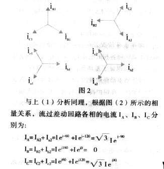
That is, under normal conditions and faults outside the protected area, the current flowing through the B-phase of the differential circuit is zero, while the current flowing through the A and C phases of the differential circuit is increased by [3(1/2)]. Times, so that when the secondary side of the transformer output short-circuit fault occurs, TA will induce a larger current, the current flowing through the differential circuit also increases, resulting in differential protection malfunction.
Through the phasor analysis of the TA secondary side connection, the TA secondary line of the secondary side of the transformer is also replaced with a and c at the terminal row. The phasor diagram is shown in Figure 3 (the symbols represent the same meaning as above). At this time, the current flowing in the differential circuit is zero (the calculation is abbreviated), so that the malfunction of the differential protection is eliminated.
It can be seen that when the phase sequence of the primary side changes, the relationship between the phasor of the secondary current of the TA should be analyzed. According to the analysis result, the secondary circuit should be changed accordingly. Sometimes it will be not only the corresponding replacement of the secondary phase sequence. Should draw attention, in short, should be carefully analyzed to prevent a differential protection caused by misoperation.
5. Differential protection secondary current circuit grounding mode error When the secondary current loop of the differential protection is grounded, the secondary current loop including the TA on each side must be connected to the grounding grid at one point. Because each substation's grounding grid points are not absolutely equipotential, there is a certain potential difference between different points. When a short-circuit fault occurs, a large current flows into the grounding grid, and larger points will be generated between the points. Potential difference. If the secondary current loop of differential protection is grounded at different points of the grounding net at the same time, the current generated by the potential difference between different grounding points in the ground net will flow into the protection secondary loop, and this current will probably increase in the differential loop. The unbalanced current causes the differential protection to malfunction.
The requirement for the secondary circuit grounding of the differential protection is that the secondary current loops on each side of the TA are connected in parallel to the differential current loop of the protection device. All secondary current loops must also be grounded only at the common point of the parallel connection. In order to avoid the influence of the current generated between different grounding points on the reliability of the differential protection action.
Third, the conclusion Differential protection is the main transformer protection, should meet the reliability, selectivity, sensitivity and quick-moving requirements. However, due to its complex structure and cumbersome wiring, it is likely to leave hidden dangers in the process of installation and overhaul. Therefore, in the process of design, construction and subsequent repairs and reconstructions, we must strictly follow the requirements of the regulations, conscientiously analyze, and ensure that each technology is closed to ensure TA model, transformation ratio, 10% error curve, secondary wiring and secondary current. The grounding method and other aspects are correct to prevent the accidental misoperation of differential protection.
I. INTRODUCTION Differential protection is the main protection method of the transformer. The principle is to reflect the difference between the inflow and outflow currents at each end of the protected transformer. In the protection zone, the current in the differential circuit is greater than the setting value, and the differential protection instantaneous Actions, and outside the protected area, transformer differential protection should not act. Transformer excitation current, wiring, TA (current transformer;) error and other factors, so that the differential circuit produces unbalanced current, unbalanced current excitation current in the presence of, often can lead to transformer differential protection misoperation It is difficult to realize transformer differential protection. Therefore, the analysis of the causes of common misoperations of transformers, so that the adoption of measures to reduce the occurrence of misoperation of transformers is the main contradiction that needs to be resolved to achieve differential protection of transformers.
Second, the common cause of misbehavior 1. TA model and the choice of transformation error Transformer differential protection should be selected with an air gap of the D-class core TA, because of differential protection on each side of the TA, the voltage level, transformation ratio Both the capacity and the magnetic saturation are inconsistent, and there is always an unbalanced current flowing in the differential circuit. The degree of core saturation directly affects the size of the unbalanced current, and it increases significantly with the increase of the primary current, and the short-circuit current is very large. In order to reduce the unbalanced current, it is necessary to take measures in the TA structure, core material, etc., so that the primary side is not easily saturated with large short-circuit currents. The D-class core TA with an air gap has the above functions and is used exclusively. Special TA for differential protection.
When selecting the TA ratio, based on the original routine calculations, according to the experience of appropriate increase in 1-2 files, that is, appropriate selection of large transformation ratio TA, this can reduce the short circuit current multiple, reduce the differential circuit generated Balancing the current effectively weakens the magnetizing inrush current and improves the sensitivity of the differential protection. This is a relatively effective method to avoid faults outside the protected area and prevent transformer differential protection from malfunctioning.
The correct choice of TA model and ratio is the basis for ensuring the reliability of differential protection operation. If the TA model is wrongly selected or the selected transformer is smaller, when the fault occurs outside the protected area, the TA core quickly saturates and the unbalanced current increases rapidly, which will cause the differential protection to malfunction. Therefore, it is necessary to pay attention to the TA model and the transformation ratio. select.
2. TA secondary circuit wiring error To make the transformer in the normal operation or in the transformer external fault, differential protection does not malfunction, it is necessary to try to adjust the TA secondary circuit wiring, so that the transformer power supply side and load side TA secondary The line current is 180° out of phase, which may cause the unbalance current flowing through the differential circuit to approach zero. In the case of a fault in the protection zone, the TA secondary line current on the power supply side and the load side of the transformer have the same phase, and the inflow difference is small. The current in the dynamic circuit is the sum of the currents on both sides, which ensures reliable operation.
Example: Three-phase two-winding transformer, rated voltage 35KV/10.5KV, Y / â–³ -11 wiring. Due to the inconsistent phase of the original secondary current of the transformer. In order to make the current in the differential circuit normal during operation and fault outside the protection zone is zero, the Y-side TA should be connected by Y/â–³-5, and the â–³-side TA should be connected by Y/Y0-12. The current in the differential circuit can be zero. As shown in Figure 1, where IA1, IB1, IC1 is the transformer high-voltage side current, Ia1, Ib1, Ic1 is the transformer low-voltage side current, IA2, IB2, IC2 is the high-voltage side TA secondary current, Ia2, Ib2, Ic2 is low voltage Side TA secondary current.
Since the transformer secondary differential protection TA has the same magnitude of secondary current amplitude, it can be obtained according to the phasor diagram:
IA=IA2+Ia2=Iei-60+Iei120=0
IB=IB2+Ib2=Iei180+Iei0=0
IC=IC2+Ic2=Iei60+Iei-120=0
That is, under normal conditions and faults outside the protected area, the currents IA, IB, and IC flowing through the differential circuit phases are all theoretically zero, thus ensuring the reliability of the differential protection operation.
Transformer differential protection often causes faulty protection due to TA secondary wiring error. Before the protection is put into operation, the polarity of the secondary circuit of the differential circuit must be carefully tested to measure the differential voltage and differential current of the differential relay to ensure the difference. The correctness of the dynamic circuit wiring.
3. The secondary load can't meet the TA10 % error curve under the maximum short-circuit current requirement. When the transformer access system capacity changes (such as replacing the power point) or before the new equipment protection is put into operation, the differential protection of the transformer is conducted in addition to the regular test inspection of the equipment according to the regulations. In addition, it is necessary to check whether the TAl0% error curve of the protection meets the requirements based on the maximum short-circuit current through the transformer and the measured secondary load value of the differential circuit when the short circuit fault in the differential protection zone is outside the fault, so as to ensure that the TA error does not exceed 10%. .
In the case of the maximum short-circuit current, the actual secondary load value of the loop exceeds the secondary maximum allowable load value that satisfies the TA10% error curve. When a three-phase short-circuit fault occurs outside the protection zone, the differential protection may malfunction, causing The switch does not have selective tripping, which directly affects the reliability of the system's power supply, and may even cause a total station blackout. In this case, the TA ratio for differential protection should be appropriately increased according to the actual situation, and the 10% error curve of TA should be rechecked to meet the requirements.
4. After the primary side commutation of TA leads to the differential protection of the differential protection TA primary side commutation, the secondary current phasor relationship should be analyzed, and respond to changes in the secondary circuit according to the analysis results, otherwise the short circuit fault outside the protection zone In this case, the differential protection of the transformer may be caused to malfunction, which is analyzed by the following example.
Example: Same as above (2) Transformer and connection method in the example, the busbar is exchanged for one reason, A and C, so that the primary phase sequence of the secondary side TA of the transformer is interchanged, while the secondary line is not moving. The following analysis of the commutation The phasor relationship of secondary currents (symbols mean the same as above):
That is, under normal conditions and faults outside the protected area, the current flowing through the B-phase of the differential circuit is zero, while the current flowing through the A and C phases of the differential circuit is increased by [3(1/2)]. Times, so that when the secondary side of the transformer output short-circuit fault occurs, TA will induce a larger current, the current flowing through the differential circuit also increases, resulting in differential protection malfunction.
Through the phasor analysis of the TA secondary side connection, the TA secondary line of the secondary side of the transformer is also replaced with a and c at the terminal row. The phasor diagram is shown in Figure 3 (the symbols represent the same meaning as above). At this time, the current flowing in the differential circuit is zero (the calculation is abbreviated), so that the malfunction of the differential protection is eliminated.
It can be seen that when the phase sequence of the primary side changes, the relationship between the phasor of the secondary current of the TA should be analyzed. According to the analysis result, the secondary circuit should be changed accordingly. Sometimes it will be not only the corresponding replacement of the secondary phase sequence. Should draw attention, in short, should be carefully analyzed to prevent a differential protection caused by misoperation.
5. Differential protection secondary current circuit grounding mode error When the secondary current loop of the differential protection is grounded, the secondary current loop including the TA on each side must be connected to the grounding grid at one point. Because each substation's grounding grid points are not absolutely equipotential, there is a certain potential difference between different points. When a short-circuit fault occurs, a large current flows into the grounding grid, and larger points will be generated between the points. Potential difference. If the secondary current loop of differential protection is grounded at different points of the grounding net at the same time, the current generated by the potential difference between different grounding points in the ground net will flow into the protection secondary loop, and this current will probably increase in the differential loop. The unbalanced current causes the differential protection to malfunction.
The requirement for the secondary circuit grounding of the differential protection is that the secondary current loops on each side of the TA are connected in parallel to the differential current loop of the protection device. All secondary current loops must also be grounded only at the common point of the parallel connection. In order to avoid the influence of the current generated between different grounding points on the reliability of the differential protection action.
Third, the conclusion Differential protection is the main transformer protection, should meet the reliability, selectivity, sensitivity and quick-moving requirements. However, due to its complex structure and cumbersome wiring, it is likely to leave hidden dangers in the process of installation and overhaul. Therefore, in the process of design, construction and subsequent repairs and reconstructions, we must strictly follow the requirements of the regulations, conscientiously analyze, and ensure that each technology is closed to ensure TA model, transformation ratio, 10% error curve, secondary wiring and secondary current. The grounding method and other aspects are correct to prevent the accidental misoperation of differential protection.
Electric Cabinet Roll Forming Machine
Electric Cabinet Roll Forming Machine,Electric Cabinet Roll Forming Machine,Electric Cabinet Forming Machinery
Cable Tray Roll Forming Machin co,.ltd , http://www.jsrollformingmachines.com