![<?echo $_SERVER['SERVER_NAME'];?>](/template/twentyseventeen/skin/images/header.jpg)
The checker of the electromagnetic flowmeter signal converter is a device for performance testing and calibration of the electromagnetic flowmeter signal converter. The existing electromagnetic flowmeter signal converter is composed of a series of high-precision resistor networks, generally only Can carry on the fixed-point test and calibration, different manufacturer's converter magnification and other parameters are different, therefore, such electromagnetic flowmeter signal converter checker can only carry on the specific electromagnetic flowmeter signal converter under the condition that does not monitor. Fixed-point testing and calibration. Limit the application of electromagnetic flowmeter II. Design Ideas:
The checker of the designed electromagnetic flowmeter signal converter includes an external electromagnetic flowmeter signal converter to be calibrated and a resistor network that outputs a fluid flow rate signal to be measured by the analog electromagnetic flowmeter. The excitation current output by the electromagnetic flowmeter signal converter is used to provide the power source and the synchronization signal, and the output signal of the analog electromagnetic flowmeter sensor is obtained. The relative size of the analog signal can be adjusted and measured steplessly; and the output signal can be adjusted according to different types of converters. It can simulate different flow rate signals and different fluid impedances. The relative amplitude of the output signal can be measured with an ordinary digital voltmeter, which can be used for verification of electromagnetic flowmeter signal converter products from different manufacturers.
Third, to achieve the program:
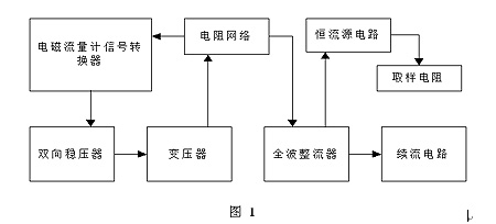
The design includes an external electromagnetic flowmeter signal converter to be calibrated and a resistance network to output the fluid flow rate signal to be measured by the analog electromagnetic flowmeter, and the excitation current output of the external electromagnetic flowmeter signal transmission converter is connected via a bidirectional voltage regulator. The primary input of a transformer, the secondary output of the transformer is connected to the input of the resistor network, and the output of the resistor network is connected to the input of a freewheeling circuit and the input of a constant current source, respectively, after a full-wave rectifier, the constant current source circuit The output is connected to a sampling resistor; the resistor network simultaneously outputs the fluid flow signal to be measured by the analog electromagnetic flowmeter and is connected to the signal input of the external electromagnetic flowmeter signal converter.
Fourth, the checker circuit implementation process:
Circuit schematic shown in Figure 2
1) The two output terminals of the electromagnetic flowmeter excitation current S1 are respectively connected in parallel with both ends of the bidirectional voltage stabilization circuit and the two input terminals of the primary coil of the transformer. The transformer secondary coil outputs a signal synchronization source and a working power supply that are electrically isolated from the S1. S2.
2) The two output terminals of transformer secondary coil output signal S2 are respectively connected to the input terminal of the resistor network and the AC input terminal of the full-wave rectifier. The DC output terminal of the full-wave rectifier is formed by the adjustable constant current source and the sampling resistor in series. The load circuit provides power, wherein the anode of the full-wave rectifier is connected to the input of the adjustable constant current source and one end of the freewheeling circuit, the cathode of the full-wave rectifier is connected to the other end of the current circuit, and the other end of the sampling resistor is connected to the output of the constant current source circuit. . When the switch SW1 of the freewheeling circuit is opened, the value I of the current I determined by the adjustable constant current source determines the positive and negative amplitude A of the positive and negative alternating current I flowing through the input of the resistor network, so that the output of the resistor network is verified. The output signal S3, S3 of the device has a positive and negative amplitude B;
B=KÐ¥A
K is the attenuation coefficient, which is determined by the resistance value in the resistor network;
3) The freewheeling circuit composed of the capacitor and the switch SW1 is connected in parallel with the DC output terminal of the full-wave rectifier. When the switch SW1 of the freewheeling circuit is turned on, the current I value A determined by the adjustable constant current source is formed on the sampling resistor. Direct measurement of the DC voltage signal S4, through the signal S4 can obtain the positive and negative amplitude A of the signal S3 alternating current I, A = S4 / R, R is the resistance of the sampling resistor.
4) When the switch SW1 of the freewheeling circuit is opened, the output signal S3 of the checker is determined by the adjustable current value i of the constant current source A, and the switch S1 of the freewheeling circuit is closed, and the switch S1 of the freewheeling circuit passes through the signal S4. Measure and obtain the positive and negative amplitude B of the actual checker output signal S3:
B=KÐ¥S4/R
The current waveforms of various parts during operation are shown in Figure 3.
The output of full-wave rectifier circuit D2 provides power for U1. U1 is an adjustable constant current source circuit. In this example, LM334 is selected. The current can be adjusted by adjusting R4. The current can be obtained by measuring the voltage across R6. When the voltage is measured by the ordinary voltmeter, the switch SW1 is turned on, and the capacitor C1 is connected to the circuit to function as a filter, so that the current source circuit can obtain a stable power input, so that stable measurement can be obtained at both ends of R6. Voltage, disconnect SW1 after measurement.
In the circuit shown in Figure 2, by adjusting the constant current source current, the resulting current is 2 microamperes to 4 milliamperes, and the output voltage range available at S3 is approximately 0 millivolts to 40 millivolts, corresponding to the measurement resistor R6. The voltage generated at both ends is about 200 microvolts to 400 millivolts, which can be measured with an ordinary digital voltmeter. Adjusting R3 and R4 can make the device adapt to the verification of electromagnetic flowmeter converters from different manufacturers. When the checker of the designed electromagnetic flowmeter signal converter works, the current waveforms of its parts are shown in FIG. 3 .
Fifth, the checker-based measurement circuit can use the PIC18LF2520 and other chips to measure the voltage signal across the resistor R6 and the square wave signal on the S3. Thus, the adjusted voltage value and the flow rate signal value can be obtained. The circuit block diagram shown in Figure 4. The hardware design of the circuit mainly includes signal conditioning, A/D conversion, LCD display and MCU-related peripheral circuits. After the voltage signal obtained by the electromagnetic flow sensor is processed by the signal conditioning circuit, the A/D converter performs analog-to-digital conversion, and then the CPU performs numerical processing, and a liquid crystal display is used to display the corresponding flow rate. The function of each module is as follows:
Sensor Signal Acquisition and Signal Conditioning Circuits: The core and difficulty is to control the polarization voltage to a repetitive and stable value, extract a weak induced electromotive force, and adjust it to an appropriate range that the subsequent circuit can handle. Due to the idea of ​​using automatic tracking feedback control, the signal conditioning circuit is controlled by a single-chip microcomputer.
A/D conversion circuit: In order to ensure the accuracy and stability of the measurement, a 16-bit ∑-Δ analog-to-digital converter is used, which has high measurement accuracy and strong anti-interference ability.
SCM related peripheral circuits: clock, reset circuit, keyboard and LCD display. The keyboard input records the initial zero point and the LCD displays the traffic in real time.
Power supply: The power supply part of the entire flow measurement system is powered by a lithium battery with a very high energy density.
Based on the checker electromagnetic flowmeter software design main program flow chart shown in Figure 5
VI. Conclusions Compared with the prior art, this design has the following salient features and significant advantages: The power supply for the use of the excitation current providing circuit eliminates the need for batteries for the usual analog signal generators; it uses an output resistor network and Constant current circuit in series, the resulting output signal is strictly symmetrical, can simulate the state of the fluid flowing in the pipe at a uniform speed; output signal and excitation signal synchronization, the signal size can be adjusted steplessly and can measure the relative size, can adapt to different manufacturers of the conversion The device is especially suitable for the performance verification of the electromagnetic flowmeter signal converter production process. Based on the electromagnetic flowmeter designed by the checker, it has been proved that the effect is good. The measurement accuracy has been greatly improved.
We started to export 10kV Transmission Line Steel Pole to Philippines from 2004 and supply more than 50,000 pcs each year.
Our firm introduced whole set of good-sized numerical control hydraulic folding equipment(1280/16000) as well as equipped with a series of good-sized professional equipments of armor plate-flatted machine, lengthways cut machine, numerical control cut machine, auto-closed up machine, auto-arc-weld machine, hydraulic redressing straight machine, etc. The firm produces all sorts of conical, pyramidal, cylindrical steel poles with production range of dia 50mm-2250mm, thickness 1mm-25mm, once taking shape 16000mm long, and large-scale steel components. The firm also is equipped with a multicolor-spayed pipelining. At the meantime, for better service to the clients, our firm founded a branch com. The Yixing Jinlei Lighting Installation Com, which offers clients a succession of service from design to manufacture and fixing.
10kV Steel Pole, Low voltage Steel Power Pole, Steel Power Tubular Pole, Steel Tubular Post
Jiangsu Xinjinlei Steel Industry Co., Ltd. , https://www.steel-pole.com