For monitoring projects, many of the causes of failures are related to improper setting of ip address, such as ip conflict, or there are several ways to monitor images are not displayed, etc., all have certain association with ip, it is very important to allocate ip address reasonably.
First, why should we allocate IP reasonably?
For small monitoring projects, the setting of ip address is relatively simple, most people will not make mistakes. For monitoring projects with more than 254 points, it is easy to make mistakes. Why?
First, if more than 254 points are not divided into network segments, let the system automatically assign an ip address, it is easy to generate ip conflicts.
Second, if the network segment is divided, the allocation of the ip address and the setting of the subnet mask become a problem. Some friends are unfamiliar with the ip address allocation and are prone to errors.
So what should I do? It is a reasonable way to divide the network segment.
Second, how to allocate IP in large networks
For monitoring over 254 points, we can assign ip addresses without dividing the network segments, but a good network planning is not only a simple and reluctant implementation function, but also needs to pay attention to the later maintenance and the clarity of the entire network. With scalability.
Let's take an example to see how to assign an ip address.
The monitoring project of a plant is divided into four areas with a total of 300 points. All the equipments are in one internal network. The main lines are connected by optical cables. There are two areas of 70 points each. The other two differences are 80 points, how to set their ip address.
Assign the following picture:
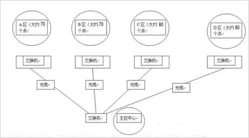
First of all, to analyze, to achieve the monitoring of these 300 points, there are two ways to achieve:
The first type: not divided into vlan, are arranged in a large network segment
The first is to not divide vlan, use a layer 2 switch, the direct ip address can be set to IP address range is 192.168.0.1-192.168.1.254, subnet mask is 255.255.254.0, a total of 500 ip addresses can be used, both It is fully contained in a large network segment.
This large network segment includes two ip segments:
192.168.0.1—192.168.0.254 Its subnet mask is 255.255.254.0.
192.168.1.1—192.168.1.254, its subnet mask is 255.255.254.0.
A total of 508 ip addresses, fully enough. Some friends may have questions about how the subnet mask of 255.255.254.0 is derived. Why is it not 255.255.255.0?
Subnet mask calculation
Here is a separate description of the IP address range 192.168.0.1-192.168.1.254, why is the subnet mask of this network segment 255.255.254.0?
This ip address range includes two ip segments.
The first ip segment is: 192.168.0.1—192.168.0.254 Its subnet mask is 255.255.255.0.
The second ip segment is: 192.168.1.1—192.168.1.254, and its subnet mask is 255.255.254.0.
In general, their common subnet mask is 255.255.254.0. Many small and medium-sized monitoring projects are intranets. In many cases, intranet projects do not need to be divided into vlans, which can save resources. However, in order to prevent network storms, port isolation can be used to ensure network security.
Second: divide vlan
For large-scale monitoring, dividing vlan is the ideal way.
Here we focus on the way to divide the network segment, using the switch can directly divide the four network segments.
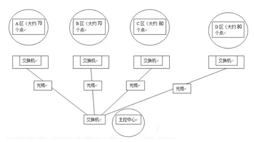
Area A address: 192.168.1.1~192.168.1.254 Mask 255.255.255.0 Gateway 192.168.1.1
Area B address: 192.168.2.1~192.168.2.254 Mask 255.255.255.0 Gateway 192.168.2.1
Area C address: 192.168.3.1~192.168.3.254 Mask 255.255.255.0 Gateway 192.168.3.1
D area address: 192.168.4.1 ~ 192.168.4.254 Mask 255.255.255.0 Gateway 192.168.4.1
Each network segment can accommodate more than 250 points. The four network segments have 1000 ip addresses that can be used. It is enough to allocate the ip address of each area. In addition, if there are any points in each subsequent area. There are enough reservations. It is worth noting that the access layer switches in this area need reasonable allocation and the choice of access layer switches. We have mentioned before, so I will not explain too much here.
So what are the benefits of dividing the network segment like this?
The ip address of the four areas is obvious. If there is a problem with that camera, you can quickly locate the problem with that camera by directly pinging the ip address. It can also effectively prevent ip conflicts. ip is a high frequency in network faults. The problem can also reduce the broadcast storm.
Third, large-scale monitoring how to choose a switch
Earlier we have already learned about the choice of monitoring IP addresses with a certain size. Let's look at how to choose a switch.
When understanding the choice of switches, let's add some basic knowledge:
Camera code stream: Before selecting a switch, you must first figure out how much bandwidth each image takes up, and this is the code stream.
Number of cameras: To figure out the bandwidth capacity of the switch. Common switches have hundreds of megabytes of switches and gigabit switches. Their actual bandwidth is generally only 60 to 70% of the theoretical value, so the available bandwidth of their ports is roughly 60Mbps or 600Mbps.
Example
Look at the single stream based on the brand of the network camera you are using, and then estimate how many cameras a switch can pick up. such as:
1.3 million: 960p camera single stream is usually 4M, with 100M switch, then you can connect 15 (15 × 4 = 60M); with Gigabit switch, you can connect 150 (150 × 4 = 600M).
2 million:
1080P camera single stream is usually 6-8M, with 100M switch, you can connect 7 (7 × 8 = 56M); with Gigabit switch, you can connect 75 (75 × 8 = 600M) These are mainstream H.264 camera for everyone to explain, H.265 halved.
Fourth, 500 way monitoring how to choose a switch
Example: How to select a switch for 500-channel monitoring
For example, there is a campus network, more than 500 high-definition cameras, and a code stream of 3 to 4 megabytes. The network structure is divided into the core layer of the access layer convergence layer. Stored in the aggregation layer, each aggregation layer corresponds to 170 cameras.
The problem: how to choose the product, the difference between 100 Mbps and Gigabit, what are the reasons for the image transmission in the network, and what factors are related to the switch...
500-channel monitoring access layer switch
The first 500 cameras, the code stream of each camera is 4M.
1. Condition 1: Camera code stream: 4 Mbps, 10 cameras are 10*4=40 Mbps.
That is to say, the access port of the access layer switch must meet the transmission rate requirement of 40Mbps/s, considering the actual transmission rate of the switch (usually 50% of the nominal value, 50M of 100M), so a hundred megabytes The switch can carry 10 cameras, 500 channels can be used to access the layer to use 50 100M switches, of course, can also be calculated by Gigabit switches.
2. Condition 2: The backplane bandwidth of the switch. If a 16-port 100-Mbps switch is selected, the bandwidth requirement of the switch backplane of the access layer is: (16*100M*2)/1000=3.2Gbps backplane bandwidth.
3. Condition 3: Packet forwarding rate: The packet forwarding rate of a 100M interface is 0.1488 Mpps/s, and the switching rate of the access layer switch is: 16*0.1488 Mpps/s=2.368 Mpps.
According to the above conditions, when a 500-channel camera is connected to the network, 50 100-Mbps access layer switches are required at this time, and the backplane bandwidth needs to be greater than 3.2 Gbps, and the packet forwarding rate is greater than 2.368 Mpps.
Convergence layer switch selection
The aggregation layer is connected and opened up, and the pressure is large. It is necessary to consider the bandwidth of the monitoring and viewing at the same time.
If there are 500 cameras in the aggregation layer and there are three switches in the aggregation layer, each of them must process the 4M code stream of 170 cameras (170* 4M=680M), which means that the aggregation layer switch needs to support the exchange of 680M or more at the same time. capacity. In this case, the general Gigabit switch can be said to be just enough (if in the actual project, if the budget is sufficient, the aggregation layer should use 4 switches as much as possible).
That is, each aggregation switch has at least seventeen hundred megabits of access from the access layer, and one gigabit port to the core switch.
In other words, the backplane bandwidth is at least: (17*100M*2)/1000+(1*1000*2)/1000=5.4Gbps
The packet forwarding rate is at least: 17*0.1488Mpps/s+1*1.488Mpps/s=3.5712Mpps/s
Of course, this is the basic configuration. In many cases, the aggregation layer basically uses the full Gigabit port, so its backplane bandwidth and packet forwarding rate are much larger.
Core layer switch selection
The core layer switch is mainly connected to the aggregation layer switch, the uplink monitoring center monitoring platform, the storage server, the digital matrix and other devices, and is the core of the entire high-definition network monitoring system. In selecting the core switch, it is necessary to consider the bandwidth capacity of the entire system and how the core layer switch is improperly configured, which inevitably results in a smooth display of the picture. Therefore, the monitoring center needs to select a full Gigabit core switch. If there are more points, you need to divide the VLAN. You should also choose a three-layer full Gigabit core switch.
Several parameters that determine the performance of the switch
In this case, the core switch needs to use at least three Gigabit ports from the aggregation layer, and some ports of the monitoring center monitoring platform, storage server, digital matrix, etc., monitoring center monitoring platform, storage server, digital matrix and other devices. There will be 8 ports to use, so we can choose a 16-port full Gigabit switch when choosing a switch.
Backplane bandwidth calculation method: 16*1000*2/1000=32Gbps.
Packet forwarding rate: 16*1.488Mpps=23.808Mpps.
In addition to the need to assess these, the core switch also needs scalability, four-layer switching, module redundancy, and routing redundancy.

The Ningbo Air-Fluid BSPT Thread Brass Nickel-Plated Push in fittings with slot structure on Brass Collet is,which is milled by Auto-CNC Machines to assure the even distance between the tooth to tooth. This way can guarantee the precision & sharp claw to catch the tube hose firmly & steadily.
The Tee Connector ,Elbow ,Y Connector and Banjo Fittings are being forged with high compactness to avoid the space inside the solid fittings' body, The Polished Surface Treatment on the Forged fittings to wipe off the burr, spot and oil,the good character is the high adhesive power of nickel plating on its Surface.
BSPT Thread Brass Nickel-Plated Push in Fittings, the Max Woking Pressure 1000 PSI and Temp Range -20 To 120 Deg ,The forged body of Elbow , Y Connector , Run Tee and Branch Tee series fittings .
BSPT Brass Nickel-Plated Push in Fittings
Brass Nickel-Plated, Air-Fluid Brass Nickel-Plated, Bspt Brass Nickel-Plated Push In Fittings
Ningbo Air-Fluid Pneumatic Components Co., Ltd , http://www.air-fittings.com
![<?echo $_SERVER['SERVER_NAME'];?>](/template/twentyseventeen/skin/images/header.jpg)